2/3 Ports Fancoil Valves
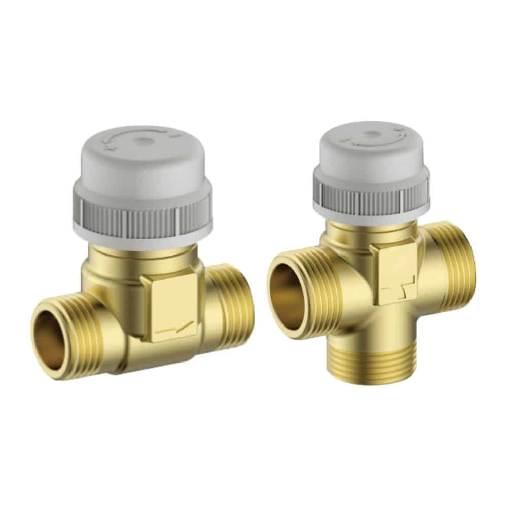
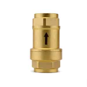
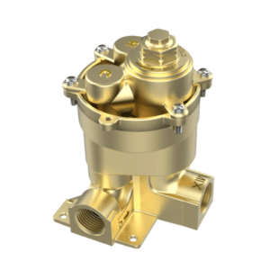
The Legom 2/3 Ports Fan Coil Valves are a complete range of thermally-actuated control valves for regulating hot or cold water flow in fan coil unit heating and air conditioning systems. Available in both 2-way (shutoff) and 3-way (diverting/mixing) configurations across three sizes — 1/2″, 3/4″, and 1″ — the range covers the full spectrum of residential and commercial fan coil unit flow control requirements. All valves use M30×1.5 threaded ring nut actuator connections compatible with standard NC thermal actuators, which are included in the package.
The 3-way valve’s plug design controls both the straight-through flow path and the by-pass flow simultaneously, enabling the same valve body to function as either a diverting valve or a mixing valve depending on installation orientation — optimising the full range of plumbing assembly requirements without requiring different valve bodies for different functions. With a plug stroke of 2.5mm, by-pass leakage of <0.02% Kvs, and compatibility with water and glycol solutions up to 50%, the range is suited to both standard hydronic and freeze-protected HVAC systems.
Key Benefits
- Complete 2-way and 3-way range in one product family – A single valve family covers both shutoff (2-way) and diverting/mixing (3-way) fan coil applications across 1/2″, 3/4″, and 1″ sizes, simplifying procurement and stock management for HVAC system integrators and installers
- 3-way valve operates as both diverting and mixing valve – The plug design controls the by-pass flow path simultaneously with the straight-through path, allowing a single 3-way valve body to be installed as either a diverting or mixing valve depending on piping orientation — eliminating the need to stock separate diverting and mixing valve bodies
- M30×1.5 actuator connection — thermal actuator included – Standard M30×1.5 threaded ring nut connection compatible with all standard NC thermal actuators. A Wisse thermal actuator is included in the package, enabling immediate installation without sourcing a separate actuator
- Ultra-low by-pass leakage of <0.02% Kvs – Extremely tight shut-off in the by-pass position minimizes unwanted flow through the closed path, improving zone temperature control accuracy and system energy efficiency
- Glycol compatible up to 50% – Works directly in ethylene glycol-water circuits at concentrations up to 50%, covering all standard freeze protection concentrations used in HVAC systems without requiring an intermediate heat exchanger
- Nickel-plated brass stem – Chemical nickel plating on the stem provides corrosion resistance and reduces friction during actuation, extending service life and ensuring consistent plug stroke across the valve’s service life
- Stainless steel spring and EPDM plug rubber – Durable, corrosion-resistant spring combined with EPDM sealing rubber provides long-term seal integrity across the full 4°C to 110°C operating temperature range
- 10 bar maximum pressure – Suitable for high-rise and commercial HVAC applications where static column pressure at lower floors is a design consideration
Technical Specifications
| Parameter | Specification |
|---|---|
| Body Material | Brass |
| Stem Material | Brass with chemical nickel-plating |
| Spring Material | Stainless steel |
| Plug Rubber | EPDM |
| Max Pressure | 10 bar |
| Min. Fluid Temperature | 4°C |
| Max. Fluid Temperature | 110°C |
| Compatible Liquids | Water, ethylene glycol solution (≤ 50%) |
| Plug Stroke | 2.5mm |
| By-pass Leakage | < 0.02% Kvs |
| Actuator Connection | Threaded ring nut M30 × 1.5 |
| Control Direction | NC (normally closed), 2-wire |
2-Way Series — Kvs Values and Dimensions
| Size | Kvs (m³/h) | A (mm) | B (mm) | C (mm) | D (mm) |
|---|---|---|---|---|---|
| DN15 (1/2″) | 1.7 | 56 | 25.5 | 15 | 40.5 |
| DN20 (3/4″) | 2.8 | 58 | 24.5 | 15 | 39.5 |
| DN25 (1″) | 3.1 | 65 | 24.5 | 15 | 39.5 |
3-Way Series — Kvs Values and Dimensions
| Size | Kvs Straight (m³/h) | Kvs By-pass (m³/h) | A (mm) | B (mm) | C (mm) | D (mm) |
|---|---|---|---|---|---|---|
| DN15 (1/2″) | 1.7 | 1.6 | 65 | 24.5 | 15 | 72 |
| DN20 (3/4″) | 2.8 | 2.0 | 65 | 24.5 | 15 | 72 |
| DN25 (1″) | 2.4 | 1.4 | 65 | 24.5 | 15 | 72 |
Refer to the datasheet flow rate curves for full pressure drop vs flow rate data across all sizes and configurations.
Application & Use Cases
- Fan coil unit on/off zone control (2-way) – The 2-way valve is installed on the supply or return connection of the fan coil unit and opens or closes on command from the room thermostat, controlling whether hot or chilled water flows through the FCU coil
- Fan coil unit diverting applications (3-way) – In a diverting configuration, the 3-way valve directs flow from a single inlet (AB port) to either the fan coil (A port) or the by-pass (B port) based on thermostat demand — maintaining constant pump flow regardless of zone demand
- Fan coil unit mixing applications (3-way) – In a mixing configuration, the 3-way valve blends flow from two inlets (A and B ports) to a single outlet (AB port), controlling the temperature of water entering the fan coil by proportioning hot and chilled water or primary and secondary circuit flows
- Two-pipe heating and cooling fan coil systems – The 2-way valve provides simple on/off zone control in two-pipe systems where the same pipework serves both heating and cooling seasonally
- Four-pipe fan coil systems – Both 2-way and 3-way valves can be applied on dedicated heating and cooling circuits in four-pipe FCU systems
- Glycol-based HVAC systems – The 50% glycol compatibility makes both series suitable for heat pump installations, cold-climate FCU systems, and any hydronic circuit using glycol as a freeze-protection additive
Installation Notes
- Valves are available with male thread connections as standard. Ensure the piping system uses compatible female thread fittings at the connection points
- The NC thermal actuator (Wisse type, included) attaches to the valve body via the M30×1.5 threaded ring nut. Hand-tighten the ring nut — do not use tools to overtighten, which can damage the actuator housing
- For 3-way diverting installations: connect the supply pipe to the AB port, the fan coil supply to the A port, and the by-pass return to the B port. Refer to the diverting configuration diagram in the datasheet
- For 3-way mixing installations: connect the primary supply to the A port, the secondary or by-pass to the B port, and the mixed outlet to the AB port. Refer to the mixing configuration diagram in the datasheet
- Flush the pipework before installation to remove grit and debris that could damage the EPDM plug rubber or lodge under the valve seat
- Select the correct Kvs size to provide adequate control authority at the design flow rate. The valve’s Kvs should give a pressure drop of at least 30–50% of the total circuit pressure drop at design flow for adequate control authority
- Connect the actuator wiring to the room thermostat output — confirm the thermostat provides an output compatible with the NC 2-wire actuator before commissioning
Frequently Asked Questions
What is the difference between a 2-way and 3-way fan coil valve?
A 2-way valve has one inlet and one outlet — it either allows flow through the fan coil (open) or blocks it (closed). When the 2-way valve closes, flow through the circuit stops entirely, which can cause pump pressure surge in systems without a differential pressure bypass. A 3-way valve has three ports and redirects flow — when it closes the fan coil path, it simultaneously opens the by-pass path, maintaining constant flow through the pump and preventing pressure surge. 3-way valves are preferred in systems with constant-speed pumps; 2-way valves are used with variable-speed pumps that can handle flow variation.
How does the 3-way valve function as both a diverting and mixing valve?
The 3-way valve’s plug controls both the straight-through path (A to AB) and the by-pass path (B) simultaneously as a pair. In diverting mode, flow enters the AB port and is directed to either A (fan coil) or B (by-pass) depending on plug position. In mixing mode, flow enters from A and B and exits through AB, with the plug controlling the proportion from each inlet. The same physical valve body achieves both functions simply by reversing the pipe connections — no different valve is needed.
What actuator is included and what voltage does it use?
A Wisse NC (normally closed) 2-wire thermal actuator is included in the package, compatible with the M30×1.5 ring nut connection on all valves in this range. The actuator operates on the thermostat output voltage — confirm the supply voltage of your room thermostat (typically 230VAC or 24VAC depending on the system) and specify the matching actuator voltage when ordering. Contact the Legom team to confirm actuator voltage options available for your market.
How do I select the correct Kvs size?
Kvs is the flow coefficient in m³/h at 1 bar pressure drop. For adequate control authority, the pressure drop across the valve at design flow should be at least 30–50% of the total circuit pressure drop. Calculate the required Kvs as: Kvs = Q / √ΔP, where Q is design flow in m³/h and ΔP is the desired pressure drop across the valve in bar. Use the flow rate curves in the datasheet to verify the selected size delivers the required pressure drop at the design flow rate. For assistance with valve sizing, contact the Legom engineering team.
What is by-pass leakage and why does <0.02% Kvs matter?
By-pass leakage is the proportion of the valve’s rated flow that passes through the “closed” by-pass path when the valve is commanded to direct full flow to the fan coil. A lower by-pass leakage means the valve closes the by-pass path more completely, providing better isolation between the fan coil circuit and the by-pass. At <0.02% Kvs, the 930019NT/2-3 way series provides extremely tight by-pass shutoff — for a DN15 valve with Kvs 1.7, this means less than 0.00034 m³/h leaks through the closed by-pass, which has negligible impact on fan coil temperature control accuracy.
OEM & ODM Customization
Legom supports OEM and ODM services for the 2/3 Ports Fan Coil Valve range. Our engineering team can customize Kvs values, pressure ratings, connection sizes, body configurations, and actuator specifications. All customization projects are handled with strict confidentiality. Contact us via WhatsApp or info@legomsmart.com.
Datasheet
Product information last reviewed by the Legom Technical Team. For the most current specifications, refer to the official datasheet or contact our sales team.
Custom OEM & ODM Solutions
Legom is a direct manufacturer offering end-to-end OEM and ODM services. With our in-house engineering and production capabilities, we work closely with distributors and system integrators to deliver fully customized solutions under strict NDA.