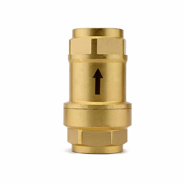
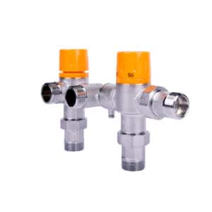
930005NT Dynamic Flow Balancing Valve
The Legom 930005NT Dynamic Flow Balancing Valve is a self-acting hydraulic flow control valve that automatically maintains a constant flow rate of 25 ± 5 L/min across a differential pressure range of 50 to 500 kPa, without requiring external power, controls, or manual adjustment. Designed for district heating systems, air handling units, fan coils, radiators, and other HVAC terminal equipment, the 930005NT ensures that each terminal in a multi-branch hydronic system receives its design flow rate regardless of pressure fluctuations elsewhere in the network.
In modern heating and cooling systems with variable pump operation and multiple terminal zones, pressure distribution across the network changes constantly as zones open and close. Without flow balancing, terminals closer to the pump receive excess flow while remote terminals are starved — causing comfort inconsistency and energy waste. The 930005NT resolves this by using an internal spring-loaded piston that automatically adjusts the variable-diameter orifice in response to differential pressure changes, maintaining constant flow in the balanced zone window of 50–500 kPa. Manufactured from Hpb59-1 brass with EPDM and high-toughness plastic seals, DN20 with G3/4″ FXF threaded connections.
Key Benefits
- Self-acting constant flow control across 50–500 kPa – Maintains 25 ± 5 L/min automatically across a ten-to-one differential pressure range without external power, actuators, or controls — using only the energy of the flowing water to operate the internal piston mechanism
- Eliminates manual hydraulic balancing – In systems using static balancing valves, commissioning engineers must manually set each valve to achieve design flow distribution. The 930005NT automatically maintains design flow at each terminal regardless of system pressure changes, eliminating the need for manual re-balancing after system modifications or zone changes
- Maintains design flow under partial load operation – When some zones are closed and system pressure redistribution occurs, the 930005NT continues to deliver design flow to the remaining open terminals, preventing over-flow conditions that waste energy and cause comfort complaints
- Works in both heating and cooling systems – Compatible with water systems from 0°C to 90°C, covering both chilled water cooling distribution and hot water heating circuits in the same product
- Hpb59-1 brass construction – High-quality leaded brass valve body provides durability and corrosion resistance in standard HVAC water circuits
- Dual seal system — EPDM and high-toughness plastic – Provides reliable sealing across the full temperature and pressure operating range of the valve
- No external power or controls required – Purely mechanical operation driven by differential pressure, with no electrical connections, control signals, or batteries needed
- OEM and ODM customization available – Flow rate, pressure range, and connection size can be customized for specific system requirements
Technical Specifications
| Parameter | Specification |
|---|---|
| Model | 930005NT |
| Valve Body Material | Hpb59-1 brass |
| Seal Material | EPDM + high-toughness plastic |
| Medium | Water |
| Connection | DN20 (G3/4″ FXF) |
| Working Water Temperature | 0°C ~ 90°C |
| Differential Pressure Range | 50 – 500 kPa |
| Flow Rate | 25 ± 5 L/min |
| Max Working Pressure | 1.0 MPa |
| Body Diameter | Ø40mm |
| Body Height | 70.8mm |
Working Principle
The 930005NT uses a spring-loaded piston inside the valve core to regulate flow across three operating conditions based on differential pressure (ΔP) across the valve:
Below 50 kPa (below minimum design pressure difference): The piston does not engage flow control. Flow increases proportionally with differential pressure — the valve behaves like an open orifice. This condition occurs only during startup or in very low-load conditions.
Between 50 kPa and 500 kPa (design operating range): The piston automatically adjusts the variable-diameter orifice in response to differential pressure changes. As ΔP increases, the variable-diameter path progressively closes while the fixed-diameter path compensates, keeping the total combined flow constant at 25 ± 5 L/min. This is the normal operating condition where the valve actively maintains design flow regardless of pressure fluctuations.
Above 500 kPa (above maximum design pressure difference): Water pressure fully closes the variable-diameter orifice. All flow passes through the fixed-diameter path only, and flow increases again with differential pressure. This condition indicates that system pressure is outside the valve’s balancing range.
The valve’s flow-vs-pressure curve shows a flat plateau between 50 kPa and 500 kPa at approximately 1.5 m³/h, confirming consistent flow delivery across the full design pressure range.
Application & Use Cases
- District heating system terminal connections – Each radiator, fan coil, or AHU connection in a district heating network receives a consistent design flow regardless of pressure fluctuations caused by other buildings or zones opening and closing on the network
- Variable flow HVAC systems with multiple zones – In systems where zone control valves open and close based on thermostat demand, residual pressure redistributes across remaining open branches. The 930005NT prevents flow runaway in open branches when other zones close
- Fan coil units in commercial buildings – Each FCU receives its design flow at all times, preventing over-cooling or over-heating due to hydraulic imbalance in large multi-zone commercial HVAC installations
- Air handling units – Maintains consistent coil water flow for accurate supply air temperature control, preventing performance degradation caused by hydraulic pressure fluctuations in the building’s chilled or hot water distribution system
- Radiator systems in multi-apartment buildings – Ensures each apartment’s radiator circuit receives its design flow without requiring manual rebalancing when other apartments adjust their heating or when district supply pressure fluctuates
- Partial load operation scenarios – When only a portion of terminals are active (partial load), the 930005NT maintains correct flow in active terminals regardless of the elevated differential pressure caused by inactive branches
Installation Notes
- The 930005NT can be installed in any orientation — the working principle diagram confirms both vertical and horizontal installation are supported
- Ensure water flow direction matches the arrow marked on the valve body. Reverse installation prevents the piston mechanism from functioning correctly
- Flush the pipeline thoroughly before installation to remove grit, scale, and debris that could lodge in the variable-diameter orifice and prevent correct piston operation
- Install isolation valves upstream and downstream to enable valve removal and servicing without draining the system
- The valve operates correctly only within the 50–500 kPa differential pressure range. Verify that the system design provides differential pressure within this range at the valve’s installation point under all operating conditions
- Use appropriate thread sealant or PTFE tape on the G3/4″ FXF threaded connections
- After installation, verify flow rate at the terminal using a flow meter or commissioning device to confirm the valve is operating within its balanced zone
Frequently Asked Questions
What is the difference between a dynamic flow balancing valve and a static balancing valve?
A static balancing valve is a manually adjustable throttling device set during commissioning to restrict flow to the design value at a specific design pressure differential. If system pressure changes — due to other zones opening or closing, pump speed changes, or network pressure fluctuations — the flow through a static valve changes proportionally. A dynamic flow balancing valve like the 930005NT uses an internal spring-loaded piston that automatically compensates for differential pressure changes, maintaining constant design flow across a wide pressure range (50–500 kPa) without any manual readjustment. Dynamic balancing eliminates the need for recommissioning after system changes and provides consistent performance under variable load conditions.
What happens when differential pressure falls below 50 kPa?
Below 50 kPa, the spring-loaded piston does not engage flow control and the valve behaves as an open orifice — flow increases with differential pressure. This condition typically occurs only during system startup when pressure has not yet built up, or in very low-load conditions where the pump is at minimum speed. Under normal operating conditions in a correctly designed HVAC system, differential pressure at the valve should remain within the 50–500 kPa balancing range.
Can the 930005NT be used in chilled water cooling systems?
Yes. The working water temperature range of 0°C to 90°C covers both chilled water cooling systems (typically 6–12°C supply) and hot water heating systems (typically 40–80°C supply). The EPDM and high-toughness plastic seals are compatible with both temperature ranges. The 930005NT provides the same hydraulic balancing function in cooling distribution circuits as in heating circuits.
Does the 930005NT require any power supply or control signal?
No. The 930005NT is a completely self-acting mechanical valve powered entirely by the differential pressure of the flowing water. No electrical connection, control signal, actuator, or external power supply is required at any point during operation. This makes it suitable for installation in locations without accessible electrical supply and eliminates the risk of loss of flow control during power failures.
What flow rate does the 930005NT maintain?
The 930005NT maintains a flow rate of 25 ± 5 L/min — meaning the actual flow will be between 20 and 30 L/min — across the full 50–500 kPa differential pressure balancing range. This tolerance band is inherent to the mechanical spring-piston design. If a tighter flow tolerance or a different flow rate is required, contact the Legom team about OEM customization options.
OEM & ODM Customization
Legom supports OEM and ODM services for the 930005NT Dynamic Flow Balancing Valve. Our engineering team can customize flow rate, differential pressure range, connection size, and body material to match specific system requirements. All customization projects are handled with strict confidentiality. Contact us via WhatsApp or info@legomsmart.com.
Datasheet
Product information last reviewed by the Legom Technical Team. For the most current specifications, refer to the official datasheet or contact our sales team.
Custom OEM & ODM Solutions
Legom is a direct manufacturer offering end-to-end OEM and ODM services. With our in-house engineering and production capabilities, we work closely with distributors and system integrators to deliver fully customized solutions under strict NDA.
