Hydronic Underfloor Heating
Hydronic underfloor heating also known as water underfloor heating is a water-based heating system that distributes heat through pipes installed beneath the floor surface. Warm water circulates through these pipes and transfers heat evenly across the floor area. Because the system operates at relatively low temperatures, it is widely used in residential, commercial, and industrial buildings where energy efficiency and long-term comfort are important.
Compared with conventional radiators or electric floor heating, hydronic underfloor heating provides more stable room temperatures and is easier to integrate with modern heat sources such as heat pumps. For this reason, it has become a common solution in new buildings and large-scale HVAC projects.
Contents
- 1 How Hydronic Underfloor Heating Works in Practice
- 2 Main Components of a Hydronic Underfloor Heating System
- 3 Installation and System Design Considerations
- 4 Hydronic vs Electric Underfloor Heating
- 5 Energy Efficiency and Sustainability
- 6 Typical Applications
- 7 Supporting System Performance with Quality Components
- 8 Frequently Asked Questions
- 9 Conclusion
How Hydronic Underfloor Heating Works in Practice
In a typical hydronic underfloor heating system, water is heated by a boiler or a heat pump and then supplied to a central manifold. From the manifold, the warm water flows into multiple floor heating circuits installed beneath the floor.
As the water moves through the pipes, heat is released gradually into the floor structure and rises evenly into the room. Once the water cools, it returns to the heat source and is reheated, forming a closed-loop system.
Room thermostats and thermal actuators control this process. When a room reaches the set temperature, the actuator limits or stops water flow to that zone. This zoning method helps reduce unnecessary energy use while maintaining consistent comfort levels.
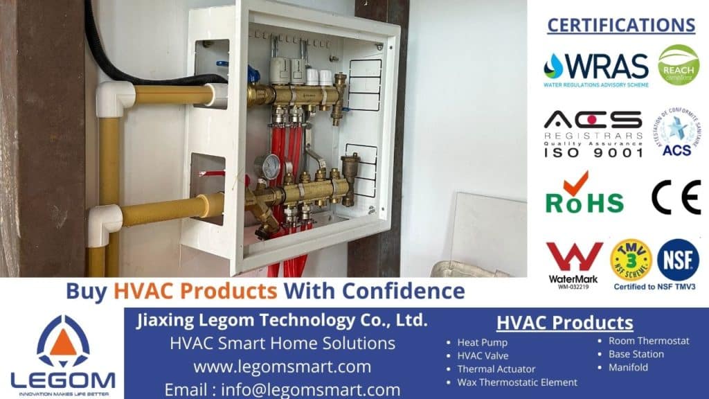
Main Components of a Hydronic Underfloor Heating System
A hydronic system relies on several key components. System performance and reliability depend heavily on the quality and compatibility of these parts.
Heating Pipes (PE-RT 5-Layer Oxygen Barrier Pipe)
The heating pipe is one of the most critical elements in any underfloor heating system. LEGOM’s PE-RT 5-Layer Oxygen Barrier Pipe is designed specifically for hydronic heating applications where long service life and stable performance are required.
This pipe uses a multi-layer structure that combines flexibility with mechanical strength. An integrated oxygen barrier layer reduces oxygen diffusion into the system, which helps protect metal components such as manifolds and valves from corrosion over time.
Because of its flexibility, PE-RT piping is suitable for various floor layouts and installation methods. When properly installed, it can operate reliably for decades in both residential and industrial environments.
Manifold (Flow Distribution and Balancing)
The manifold functions as the distribution center of the hydronic system. It directs hot water from the heat source into individual floor heating circuits and collects the return flow.
In practical installations, a well-designed manifold allows installers to balance flow rates across different zones. This ensures that each area receives the appropriate amount of heat, even in buildings with varying room sizes or heat demands.
LEGOM manifolds are designed to support multi-zone systems and provide connection points for thermal actuators, making temperature control more precise and easier to manage.
Thermal Actuator (Automatic Flow Control)
Thermal actuators are installed on the manifold valves and work directly with room thermostats. When the thermostat signals a demand for heat, the actuator opens the valve to allow water flow. When the target temperature is reached, the valve closes.
This automatic control reduces energy waste and improves overall system efficiency. In larger installations, actuators are essential for zone-based heating and consistent indoor comfort.
LEGOM thermal actuators are designed for stable operation, low power consumption, and compatibility with common manifold systems.
Room Thermostat (Temperature Control Interface)
The room thermostat is the main user interface of the system. It measures room temperature and sends control signals to the actuators.
Modern thermostats allow users to set different temperatures for different rooms and, in some cases, schedule heating based on occupancy. This level of control is particularly useful in commercial and industrial buildings where heating demand varies throughout the day.
LEGOM room thermostats are designed to integrate smoothly with hydronic floor heating systems and support accurate temperature regulation.
Installation and System Design Considerations
Pipe Layout and Spacing
Pipe spacing is usually designed according to heat demand and floor construction. In most projects, spacing ranges between 100 mm and 200 mm. Correct spacing helps avoid cold spots and ensures even heat distribution. Ultimately, pipe spacing varies depending on room function and heating demand, as shown below.
| Application Area | Typical Pipe Spacing | Heat Demand Level | Notes |
|---|---|---|---|
| Living areas | 150–200 mm | Medium | Standard spacing for most residential spaces |
| Bathrooms | 100–150 mm | High | Tighter spacing improves comfort in high-demand areas |
| Office spaces | 150–200 mm | Medium | Balanced for comfort and efficiency |
| Industrial areas | 100–150 mm | High | Suitable for larger heat loads |
| Low-demand zones | Up to 200 mm | Low | Used in well-insulated areas |
Heat Source Selection
Hydronic underfloor heating systems can be combined with various heat sources, depending on building size, energy strategy, and long-term operating goals.
In practice, gas boilers are commonly used in small to medium installations, heat pumps are preferred in larger or energy-efficient buildings, and renewable energy systems are often added to reduce overall energy consumption.
The table below summarizes the most common heat sources used with hydronic underfloor heating systems, along with their typical applications and performance characteristics.
| Heat Source | Typical Application | Energy Efficiency | Initial Cost | Operating Cost | Notes |
|---|---|---|---|---|---|
| Gas Boiler | Small to medium buildings | Moderate | Lower | Medium | Common choice for retrofit projects and buildings with existing gas infrastructure |
| Heat Pump (Air-to-Water) | Medium to large, energy-efficient buildings | High | Higher | Low | Works best with low-temperature systems such as hydronic underfloor heating |
| Heat Pump (Ground Source) | Large buildings with long-term use | Very high | High | Very low | Requires higher installation cost but offers stable performance and long-term savings |
| Solar Thermal (Hybrid) | Supplementary heating systems | High (when available) | Medium | Very low | Typically combined with boilers or heat pumps for seasonal support |
| Biomass Boiler | Rural or off-grid applications | High | Medium–High | Low | Uses renewable fuel; requires space for fuel storage |
Floor Construction
After the pipes are installed, they need to be properly supported and protected by the floor structure above them. The floor construction layer not only secures the piping in place, but also plays an important role in heat transfer and temperature stability. Different floor construction methods provide different levels of thermal mass, installation speed, and suitability depending on whether the project is a new build or a renovation.
The table below outlines the most commonly used floor construction options in hydronic underfloor heating systems and their typical characteristics.
| Floor Construction Type | Typical Thickness | Thermal Performance | Installation Notes | Common Applications |
|---|---|---|---|---|
| Concrete Slab | 50–100 mm | High thermal mass | Pipes are embedded directly into the slab during construction | New buildings, industrial facilities |
| Cement Screed | 40–70 mm | Medium–High | Common in residential and commercial projects; allows easier leveling | Homes, offices, commercial spaces |
| Anhydrite Screed | 35–60 mm | High | Faster heat transfer and smoother surface; requires moisture control | Modern buildings, large floor areas |
| Dry System Panels | 20–30 mm | Medium | Lightweight solution; faster installation with less curing time | Renovation projects, upper floors |
| Floating Floor Systems | Varies | Medium | Requires proper insulation to reduce heat loss | Residential retrofits |
Hydronic vs Electric Underfloor Heating

electric underfloor heating
| Aspect | Hydronic System | Electric System |
|---|---|---|
| Heat medium | Water | Electricity |
| Energy efficiency | High | Moderate |
| Operating cost | Lower over time | Higher |
| Area coverage | Large areas | Limited areas |
| Typical lifespan | 25–50 years | Shorter |
In practice, electric systems are often used for small rooms or renovation projects, while hydronic systems are better suited for large buildings and long-term operation. A more detailed discussion of system differences is available in this comparison of Hydronic and Electric Underfloor Heating.
Energy Efficiency and Sustainability
Hydronic underfloor heating systems operate at lower temperatures than traditional radiator systems. This makes them well suited for heat pumps, which perform more efficiently at low supply temperatures.
With proper zoning and control, hydronic systems can significantly reduce energy consumption while maintaining indoor comfort. This is one of the main reasons they are widely used in energy-efficient building designs.
Typical Applications
Although, hydronic underfloor heating is used across a wide range of building types due to its ability to deliver even heat distribution, stable indoor temperatures, and long-term energy efficiency. The suitability of the system still depends on factors such as floor area, operating hours, and heating demand. In general, hydronic systems perform best in buildings with larger spaces or continuous heating requirements.
The table below shows common building applications and how well hydronic underfloor heating fits each use case.
| Application | Suitability |
|---|---|
| Residential housing | Very suitable |
| Office buildings | Suitable |
| Industrial facilities | Highly suitable |
| Warehouses | Suitable |
| Large commercial spaces | Recommended |
Supporting System Performance with Quality Components
In hydronic underfloor heating, long-term performance depends not only on system design but also on component quality. Reliable pipes, well-balanced manifolds, responsive actuators, and accurate thermostats all contribute to stable operation.
Manufacturers such as LEGOM focus on providing system components that support efficient heat distribution, precise control, and long service life across different project scales.
Frequently Asked Questions
- Is hydronic underfloor heating energy efficient? Yes. It operates at lower temperatures and works efficiently with heat pumps.
- How long do hydronic heating pipes last? High-quality PE-RT pipes can last 25–50 years when installed correctly.
- Can the system be zoned? Yes. Manifolds, actuators, and thermostats allow independent control of different areas.
- What floor finishes are suitable? Concrete, tile, stone, and engineered wood are commonly used.
Conclusion
Hydronic underfloor heating offers a reliable and efficient solution for modern buildings. By combining water-based heat distribution with properly designed components, the system delivers even comfort and long-term energy savings.
When supported by quality components such as multi-layer PE-RT pipes, manifolds, thermal actuators, and thermostats, hydronic underfloor heating becomes a practical and durable HVAC solution for residential, commercial, and industrial applications.
Last reviewed: January 2026