

Most guidance on underfloor heating pipe layout spends its time on spiral versus serpentine. That is the easy question, and it is not the one that decides whether the finished floor feels even underfoot.
Spacing decides that. A well-spaced serpentine beats a badly spaced spiral every time, and no pattern rescues a floor where the centres were set to whatever looked about right on the day. The pattern is the frame. The spacing is the craft.
So this guide covers both, in proportion. The patterns briefly, then spacing properly: the range and what each step buys you, why the edge of a room needs different treatment from the middle, how the floor covering can quietly undo the whole calculation, and the loop length limit that caps how much floor one circuit can serve.
The Layout Patterns
There are two base patterns and two useful variations on them.
| Layout | Best For | Heat Distribution | Installation |
|---|---|---|---|
| Spiral (counterflow) | Any shape, including awkward ones | Self-evening: supply and return alternate | Wide bends, easier on the pipe |
| Single serpentine | Square or rectangular rooms | Warmest at the start of the run, cooler at the end | Fast, but 180° bends at every turn |
| Double serpentine | Long rectangular rooms | More even than single: return runs beside supply | Slightly more setting out |
| Edge zone variant | Rooms with large glazing or cold walls | Compensates for the cold perimeter | Needs the heat loss worked out first |
Spiral or Counterflow Layout
The pipe runs inward from the room perimeter to the centre in a widening spiral, then returns outward through the gaps left on the way in. The important consequence is that every warm supply run sits beside a cooler return run.
That is why the spiral self-evens. The floor temperature at any point is the average of a hot pipe and a cool one, so the whole surface sits within a narrow band rather than grading from one side of the room to the other. It also means the bends are wide and gradual, which is easier on the pipe and faster to lay than it looks.
This pattern suits irregular rooms well, because a spiral can follow almost any outline. The common objection, that it is only for small rooms, is not really true; it is the pattern most installers reach for once they have laid a few.
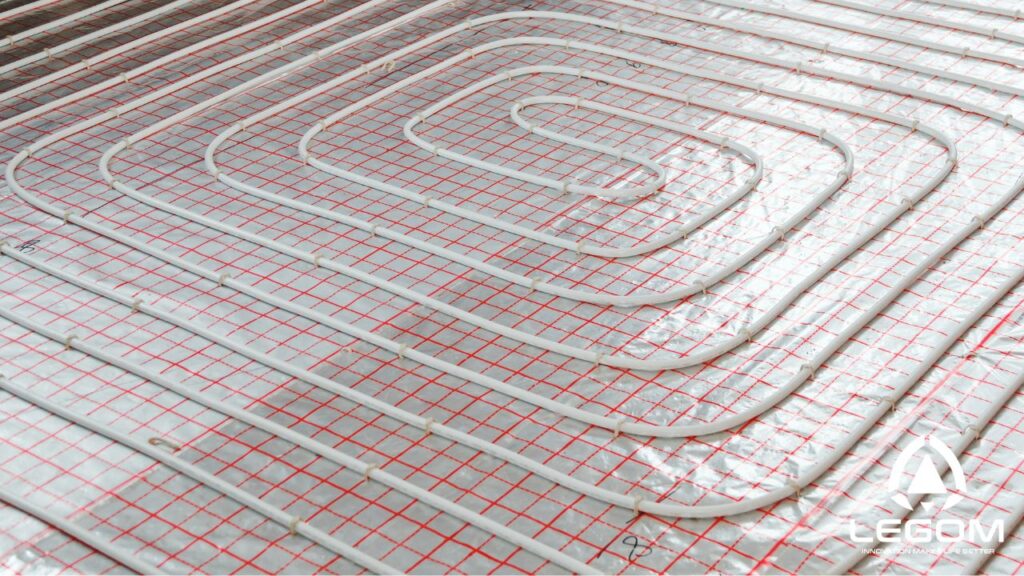
Spiral Layout of Water Underfloor Heating Pipes
Single Serpentine Layout
The pipe runs back and forth in parallel rows from one side of the room to the other. Quick to set out and quick to lay, which is why it is common.
The trade-off is inherent rather than a question of workmanship. Water cools as it travels, so the first rows laid are warmer than the last. Over a long run that becomes a noticeable gradient across the room, warmest where the supply enters. Tighter spacing does not remove the gradient, it just reduces the output difference across it.
So a single serpentine is a reasonable choice in a modest, regularly shaped room, and a poor one in a large open space where the gradient has room to develop.
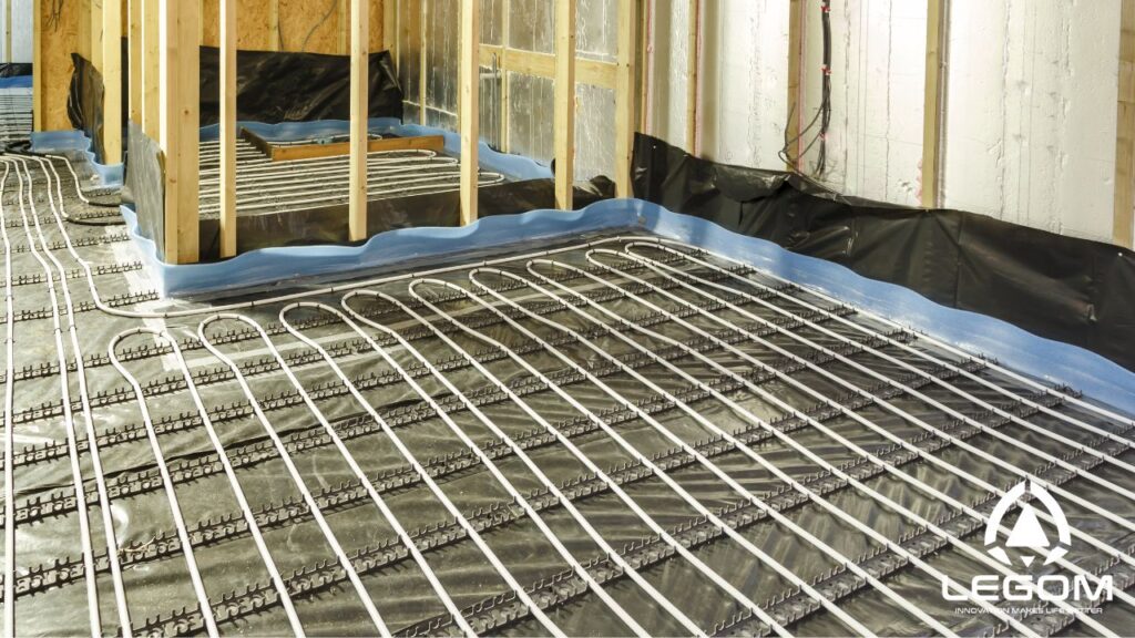
Serpentine Layout (Single Serpentine) of Water Underfloor Heating Pipes
Double Serpentine
The fix for the gradient. The pipe runs out across the room at double the final spacing, then returns along the gaps, so supply and return alternate in the same way a spiral does.
It gives much of the spiral’s evenness while keeping the straight-line setting out of a serpentine, which makes it the usual answer in long rectangular rooms and corridors where a spiral would be awkward.
Edge Zone Variant
Not a separate pattern so much as a modification applied to any of the above, and it is covered in the spacing section below because that is what it really is.
Pipe Spacing: The Decision That Matters Most
Spacing, or pipe centres, is the distance between adjacent runs. It is set at the design stage from the room’s heat loss, and it is the single biggest lever on output and evenness.
The Range and What Each Step Buys
The working range is 100 mm to 200 mm, occasionally stretching to 300 mm in very low-demand areas.
| Spacing | Pipe per m² | Relative output | Typical use |
|---|---|---|---|
| 100 mm | 10.0 m | Highest | Edge zones, bathrooms, high heat loss rooms |
| 150 mm | 6.7 m | Baseline | The usual main field spacing |
| 200 mm | 5.0 m | Roughly 15 to 20% below baseline | Well-insulated rooms, low heat loss |
| 300 mm | 3.3 m | Low, and evenness suffers | Rarely justified; warm and cool stripes become detectable |
Two things to take from that table.
The pipe quantity calculation is simple. Pipe length equals floor area divided by spacing in metres. At 150 mm centres, every square metre needs 6.67 m of pipe. Add the run from the manifold to the room and back for each loop. This is the number to use when ordering.
Tighter is not indefinitely better. Output rises as spacing closes, but the ceiling is not the pipe, it is the floor surface temperature. EN 1264 limits the surface to around 29 °C in the occupied zone, which caps output at roughly 100 W/m² with a 20 °C room. Once you are at that ceiling, closing the spacing further achieves nothing except using more pipe and shortening the loop you can lay.
Edge Zones at External Walls
This is where an experienced layout differs visibly from a software default.
Heat loss is not uniform across a room. It concentrates at external walls and especially at large glazing, where the cold surface pulls heat out and generates a downdraught. A room laid at uniform 150 mm centres will have a cool strip along the glazing and be comfortable everywhere else.
The answer is a peripheral or edge zone: tighter spacing, typically 100 mm, in a band roughly 0.5 m to 1 m wide along external walls and across the front of large glazed areas, with the main field at 150 mm or 200 mm behind it.
The standard allows for this explicitly. EN 1264 permits a higher surface temperature in peripheral zones, around 35 °C against 29 °C in the occupied zone, which raises the output ceiling in that band to roughly 175 W/m². The reasoning is that nobody stands still on the strip immediately against a window.
Bathrooms get similar treatment for a different reason: people stand on wet feet, so the standard permits around 33 °C surface there, and tighter spacing is normal.
The Floor Covering Can Undo All of It
This is the failure that surprises people after the floor is down, because the system is working exactly as designed and still underperforms.
Everything above assumes the heat can get out of the floor. The covering sits in the way, and its thermal resistance decides how much gets through. EN 1264’s characteristic curves assume a covering resistance of no more than 0.15 m²K/W, and that figure is a practical ceiling rather than a suggestion.
Roughly where common coverings fall:
- Ceramic and porcelain tile, stone: negligible resistance. Best performers, and what the output figures above assume.
- Vinyl and LVT: low. Works well.
- Engineered wood, 14 mm: moderate, often 0.10 to 0.13. Usable, but it consumes most of the allowance, so the spacing or flow temperature has to compensate. See underfloor heating for wooden floors.
- Carpet with underlay: frequently over the limit once the underlay is counted. This is the common one. A thick underlay can push the build-up past 0.15 m²K/W on its own and leave a correctly designed floor unable to reach setpoint.
Decide the covering before finalising the spacing, not after. If the covering is unknown at design stage, assume a resistance near the limit and space accordingly, because tightening the spacing later means lifting the floor.
Loop Length Limits, and Why They Cap Room Size
A loop is one continuous length of pipe from the manifold and back. Its length is limited by pressure drop: push water through too long a circuit and the circulator cannot deliver the design flow, so the far end runs cold whatever the spacing.
Working maximums by pipe size:
- 12 mm: roughly 60 to 80 m
- 16 mm: roughly 100 m
- 17 mm: roughly 120 m
- 20 mm: roughly 120 to 150 m
Combine that with the spacing table and the maximum floor area per loop falls out. A 100 m loop of 16 mm pipe at 150 mm centres covers about 15 m², less the run to and from the manifold. At 200 mm centres the same loop covers about 20 m². At 100 mm centres, only about 10 m².
That arithmetic is what determines how many loops a floor needs, and therefore the manifold size. A 60 m² open-plan room at 150 mm centres needs four loops, not one, which means a four-port manifold minimum for that room alone. Our manifold specifications page covers port counts and connection sizes.
Two rules that make the result workable:
Keep loops on one manifold within roughly 10 to 15 percent of each other in length. Flow meters can throttle a fast loop, but they cannot rescue a 40 m loop sharing a manifold with a 110 m one. Design the loops to similar lengths from the start.
One loop per room wherever the room is small enough. A loop that crosses two rooms cannot be zoned separately, whatever the controls do afterwards.
Minimum Bend Radius
Worth a short section because kinking pipe is unrecoverable: the damaged section has to be cut out, and if it is already in the screed that means breaking out the floor.
For PE-RT and PEX, the minimum bend radius without support is around five times the outside diameter. For 16 mm pipe that is about 80 mm, so roughly a 160 mm turn. With a bending former or support bracket you can go tighter, commonly three to four times the diameter.
This is the practical reason the spiral pattern is easier to lay. Its turns are gradual throughout, whereas a serpentine makes a 180° turn at the end of every row, and at 100 mm centres that turn is close to the limit.
Where the Movement Joints Go
Joint positions have to be settled before the loop layout, not after, and this is one of the most common sequencing mistakes on site.
A heated screed is divided into bays, and those bay boundaries are fixed by the screed rather than by the pipe. Two rules then constrain the layout:
Each loop stays within one bay. Design the loops around the bays, which often means more loops than the room area alone would suggest.
Only the flow and return tails cross a joint, in one level, and each must be sleeved. A flexible sleeve of about 0.3 m centred on the joint leaves the pipe debonded either side so it can move with the screed instead of being gripped by it. Without the sleeve the joint cannot open, the movement goes into a crack somewhere else, and the pipe takes a shear load it was not designed for.
For the bay size limits, the positions joints have to occupy, and the detail of the sleeving, see our guide on where the movement joints go. Read it before setting out the loops.
Planning and Installation Sequence
1. Room-by-Room Heat Loss
Everything starts here. Spacing, loop count and flow temperature all follow from the heat loss figure for each room, and no layout decision can be made sensibly without it. Guessing at this stage is what produces the floor that never quite gets there.
2. Insulation Below the Pipe
Without insulation under the pipe, a meaningful share of the output goes downward. Ground floors need more than intermediate floors, since below an intermediate floor is another heated space. See insulation boards for underfloor heating and types of floor insulation.
3. Set Out Bays, Then Loops
Mark the movement joints first, then the loops within them, then the pipe route back to the manifold. Not the other way round.
4. Fix the Pipe
Four common methods, and the choice affects how consistently the spacing holds:
- Staples or tackers driven into EPS insulation. Fast, but spacing depends entirely on the installer’s eye.
- Clip rail fixed to the substrate, with pipe clipped in at marked intervals. Spacing is repeatable.
- Cable ties to steel mesh. Secure, and the mesh grid gives a spacing reference.
- Castellated or studded panel. Pipe is pushed between moulded studs, so the spacing is fixed mechanically. The most consistent option, and worth considering precisely because spacing is the thing that matters most.
Hold the pipe securely but not under tension. And do not run pipe where it cannot do any useful work: under kitchen base units and islands, under built-in wardrobes, under panelled baths, or within about 50 mm of walls. Output there is wasted and in a sealed cabinet the heat is simply trapped.
5. Connect to the Manifold
Loops begin and end at the manifold, not at the heat source. The heat source connects to the manifold’s primary side, and where its water is hotter than the floor can accept, a blending group reduces it. See underfloor heating mixing valves.
Label each loop at the manifold as it is connected. Nobody can identify eight unlabelled tails three weeks later.
6. Pressure Test, and Photograph Everything
Pressure test before the screed goes down: typically 6 bar held for 24 hours, checking for any drop. Then keep the circuits pressurised through the pour, so damage caused by screeding shows up immediately rather than in year three.
Photograph every loop before it disappears. This is the most valuable record the building will ever have, it costs nothing, and anyone who later needs to drill the floor or trace a leak will need it.
7. Cure, Then Commission on the Curve
The step most often compressed under programme pressure, and compressing it cracks floors that were otherwise laid correctly.
A sand and cement screed should not be heated for at least 21 days after laying. An anhydrite screed, at least 7 days, subject to the manufacturer’s figure. Then:
- Water in at no more than 25 °C for at least three days
- Raised to maximum design flow temperature for a further four days
- Cooled down, but not below 15 °C, before the floor covering is laid
Record the dates and temperatures. Many covering manufacturers require that evidence before honouring a warranty.
8. Balance, Then Set the Controls
Once the system is up to design temperature, set each loop’s flow meter to its calculated flow rate, leaving the longest and most resistant loop fully open. Only then configure the thermostats. Setting controls on an unbalanced manifold produces complaints that look like control faults and are not.
Purge each loop individually if any circuit reads low or unsteady, since air blocks circulation as effectively as a closed valve. See how to bleed underfloor heating. For the control side, see underfloor heating sensors and our room thermostats.
Standards to Specify Against
“ISO and DIN standards” is not a specification. The ones that matter:
- EN 1264, the water-based underfloor heating system standard. Parts cover design, output calculation, installation and commissioning, including the surface temperature limits and the heat-up schedule above.
- DIN 4726, the oxygen barrier requirement. Pipe without an EVOH barrier lets oxygen diffuse through the wall, which produces the magnetite sludge that later blocks valves and wears pumps.
- EN ISO 15875 for crosslinked polyethylene (PEX) and EN ISO 22391 for raised temperature polyethylene (PE-RT).
Ask for the specific standard and the test report, not a general claim of compliance.
Legom Underfloor Heating Components
Jiaxing Legom Technology Co., Ltd. manufactures hydronic underfloor heating components from our facility in Jiaxing, Zhejiang, supplying more than 90 countries.
Our floor heating pipe carries an EVOH oxygen barrier to DIN 4726 in 16 mm, 17 mm and 20 mm sizes, which covers the loop length range above. Because loop count follows from the spacing and bay arithmetic rather than from room count, we supply manifolds in stainless steel and brass from 2 to 13 circuits with integral flow meters for balancing.
Around those we make thermal actuators and the wax elements inside them, room thermostats and wiring centres, and the mixing valves for the blending group, so a complete system comes from one supplier with one set of documentation.
Send us the floor plan with the room heat losses and we will work through the spacing, loop count and manifold specification with you. For non-standard port counts or cabinet dimensions, our OEM and ODM service covers it. Cost context across the whole installation is in wet underfloor heating cost and installation considerations.
Frequently Asked Questions
What is the ideal underfloor heating pipe spacing?
150 mm is the usual main field spacing. Tighten to 100 mm in edge zones along external walls and large glazing, and in bathrooms. Open to 200 mm in well-insulated rooms with low heat loss. The figure should come from the room heat loss calculation rather than a default.
How much pipe do I need per square metre?
Floor area divided by spacing in metres. At 100 mm centres, 10 m per m². At 150 mm, 6.7 m. At 200 mm, 5 m. Add the run from the manifold to the room and back for each loop.
Does closer spacing always give more heat?
Up to a point. Output rises as spacing closes, but the ceiling is the floor surface temperature, limited to around 29 °C in occupied areas, which caps output at roughly 100 W/m². Once there, tighter spacing only consumes pipe and shortens the loop you can lay.
What is the maximum loop length?
Roughly 100 m for 16 mm pipe, 120 m for 17 mm, and 60 to 80 m for 12 mm. Exceed it and pressure drop prevents the circulator delivering design flow, so the far end of the loop runs cold regardless of spacing.
How much floor can one loop cover?
A 100 m loop of 16 mm pipe covers about 15 m² at 150 mm centres, about 20 m² at 200 mm, and only about 10 m² at 100 mm, less the run to and from the manifold. That arithmetic sets the loop count and therefore the manifold size.
Spiral or serpentine: which is better?
Spiral, in most cases. Supply and return alternate so the floor temperature self-evens, and the bends are gradual. A single serpentine is inherently warmer at the start of the run than the end, which is a property of the pattern rather than a workmanship issue. A double serpentine recovers most of the spiral’s evenness while keeping straight-line setting out.
Can I lay underfloor heating under carpet?
Only with care. EN 1264 assumes a floor covering resistance of no more than 0.15 m²K/W, and carpet with a thick underlay frequently exceeds that on its own. The result is a correctly designed floor that cannot reach setpoint. Decide the covering before finalising the spacing.
Should pipes run under kitchen units and baths?
No. Output under a sealed base unit, an island or a panelled bath is wasted and the heat is trapped. Keep the pipe out of those areas, and about 50 mm clear of walls, and allow for it when calculating the heated area.
“If I had to point to the one decision that determines whether an underfloor heating floor feels even underfoot, it is pipe spacing, not which layout pattern you pick. People obsess over spiral versus serpentine, but a well-spaced serpentine outperforms a badly spaced spiral every time. The 100 to 200 mm range exists for a reason: tighter spacing near cold zones like external walls, wider spacing in the room centre, is how an experienced installer evens out the floor temperature. The pattern is just the frame. The spacing is the craft.”
— Maggie Shen, Director of Legom
Reviewed by Maggie Shen, Director at Legom, on October 15, 2026. This article was reviewed for technical accuracy, including the pipe quantity calculation by spacing, the EN 1264 surface temperature limits for occupied, bathroom and peripheral zones, the 0.15 m²K/W floor covering resistance ceiling, loop length maximums by pipe diameter, the minimum bend radius of five times outside diameter, movement joint sequencing and pipe sleeving, the 6 bar pressure test, and the curing and commissioning heat-up schedule.